Inhaltsverzeichnis
Timing Bus requirements
We have two types of measurement / receiving / sending modules:
- time critical modules
- Non-Time critical modules
Time Critical means that the measured data will be useless if a very accurate timestamp can not be applied to it. Non-time critical means that a less accurate timestamp is good enough. Non-time critical data would be the generic sensor measurement data like radiation, temperature and other envoironmental sensors. Time-critical data is measurement data like satellite radio that need to be used for satellite communication.
Solution
The timing bus will consist of two parts, a high accuracy timing line and a low accuracy timing port. Low- and High Accuracy timestamps will be transmitted separately.
Low accuracy
The low accuracy timing port will be sending out information containing a timestamp ( example format might be in the format of „YYYY-MM-DD hh:mm:ss“ (YYYY = year, MM = month, DD = day, hh = hour (0-24)), mm = minutes, ss = seconds). The BUS used for this will be RS485 with the timing module broadcasting the time on it. Measurement modules are using that bus readonly, timing modules read/write.
High accuracy
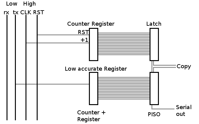
The high accuracy timing port will be sending a 10Mhz (currently wip, actual frequency to discuss) clock that is highly stabelized to all modules. It will also send a RESET signal. Every measurement module will track the timing clock and count the clocks in a register (use 24 bit for 10Mhz). The reset pin will be used to reset the 24 bit register to 0. It will be triggered by the timing module every second. Thus we have a very exact pulse every 1 second and can use the contents of the register to count on in the 1 second timeframe.
To get the most accurate timing information, the measurement module will put a pin to high and the timing logic will copy the actual timing information into a buffer where it can be read from serially.
Schematic
Addition to this image… The microcontroller reading the low accuracy timing signal will also get the pps / reset signal.
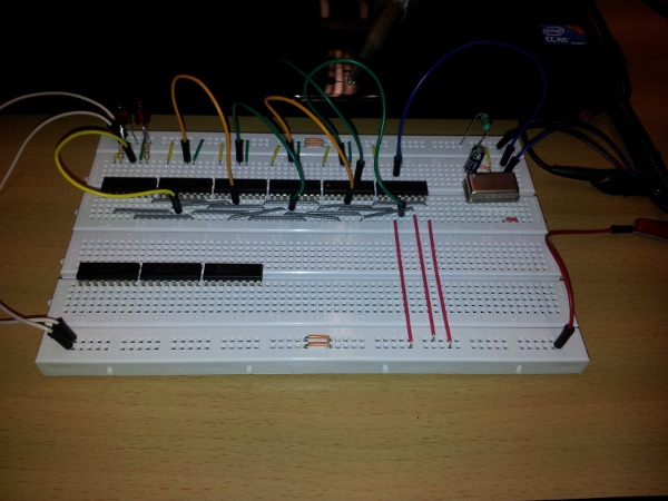
Current experimentation stage 2011-01-07 21:49 CET
We're currently experimenting with 10Mhz Oscilators and 4Bit Counters. Our current test-setup looks like this:
Challenges
- The timing bus should always send information on the following second. RST/PPS makes this info valid.
- since the 10mhz signal is likely to drift, the timing module should send information on the drift rate in the last second. This information can be calculatex by counting the cycles and them subtracting 10.000.000 (10 million ticks).
- for messuring the modules will send the timestamp (low precisision signal), the counter in the PISO and he most current drift information.
- better timng modules could use a temperature and voltage controlled oscilator to make a more stable synchronisation signal
Optimisatin
- FPGA/CPLD instead of discrete logic


