Inhaltsverzeichnis
Math and Build instructions on lowpass filters
Lowpass Filters are to be used for filtering out higher frequency noise. For example: We have a signal with 1.5 Mhz, we have some noise with 2 Mhz, so let's filter the noise out to just keep the signal we want. There are different kinds of basic Lowpass Filters, LC-, RC and RL Filters. Theese basic filters always consist of two elements out of L, R and C which are Inductor (L), Resistor (R) or Capacitor (C). Higher order filters can be built by combining basic filters.
Most of our current findings apply to LC Filters. Here's some stuff about it.
LC-Lowpass Filter
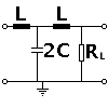
What is being discussed here is a filter element looking like this:
This Lowpass filter is made of 2 LC filters and a terminating Resistor (R_L). The terminating Resistor can be omited if not needed (?) but is shown in the graph because we will be calculating it here. It's called a T-Filter. Note: Imput and output of the filter must be matched to the system impedance (e.g. 50 Ohm).
What we expect
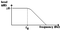
Since it's a low pass we assume that any signal under a cutoff frequency (f_g) will pass it. Any signal with a higher frequency than the cutoff frequency will be weakened. The higher the frequency the more it will be weakened.
Thus, what we expect can be seen in this picture.
Formulas
The Formulas will be used to perform calculations on a base filter, not on the filter in the picture shown above. To perform calculations for this filters, the formulas are needed.
How this was used, when we built filters
Since we did not have a device for measuring an Inductor but very just inductors (1%) we decided to use one of the inductors. We set our Cutoff Frequency and calculated the needed values. Calculations were performed for one of the base filters (LC). Thus we took two inductivities (L) from the stack and one Capacitor with double the size as for one filter (the picture above says 2C).
Forget formulas for more complicated filters but use simulation tools instead! There is a very old DOS based software „PUFF“ which shows the frequency and phase response of a given filter, consisting of lumped constant components as L, C, R and (!) transmission lines (traces on the pcb).
A few words on HF
As we have found out while experimenting, in HF almost everything becomes a lowpass, but not in the way we wanted it to be. Things on how to make the PCBs should be added here.
If the wavelength is less than approx. 10 to 100x the size of your components or wires in the circuitry, you will have lots of parasitic effects due to line inductance or stray capacitance which alter network behaviour. Example: At frequencies about 1 GHz, (wavelength 30 cm) you cannot use wires etc. longer than some millimeters without considering its parasitic effects.
Errata
If you find errors, please tell or fix them (this is a wiki after all).


