Inhaltsverzeichnis
HGG: The backplane (friendship)
The friendship module is the backplane of any HGG groundstation. This is basically the board where the extension cards are plugged in to. It is the backplane for the bus used by the modules to carry measured data, timing information and all other things over. Thus friendship connects everything.
Design decissions
For simplicity the cards are connected over a low speed data bus that will carry a protocol named Magic. This bus will use RS485 for communication since it can be used with most microcontrollers and there are existing cores for it for FPGA and CPLD. The slow speed data bus is mandatory to support for all modules. Modules must be able to cope with a system that only supports the slow speed bus. A high speed data bus is currently not supported and subject to later development. About 32 pins in the connectors have been reserved for that purpose.
The connectors used for the module cards are physically (but not electrically) PCI-Express x4 Slots. Those are reasonably cheap and generally available at electronic shops.
One of the ports is special, it is the port for the busmaster. The busmaster controls the stuff that happens on the bus and is also controlling the bus protocol. The busmaster port has an additional set of pins at the front of the PCIe slot. Thus not more than 1 busmaster can be present on the bus. Please refer for a busmaster port extension at the bottom of this document.
Only few things should happen on the backplane board. It is mainly a bus system and nothing more. So there's just the slots and a few components on that board.
Overview of the pinning / Design
The design for PCIe x4 slots and Cards can be found in the HGG git repository on github (direct link: https://github.com/shackspace/hgg/tree/master/hgg/libs/eagle). It contains an eagle library we use in our designs. Currently only one side of the PCIe slots is used, the other pins are reserved for extensions (like for example a high speed bus).
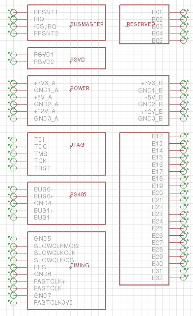
The bus looks like this in the schematic:
The schematic divides the pins by responsibility:
BUSMASTER
- PRSNT1 … Connect to PRSNT2 to indicate that the card is present
- IRQ … this card requests a bus transmission (active low)
- /CS … this card is selected to perform a bus transmission (active low)
- PRSNT2 … Connect to PRSNT1 to indicate that the card is present
POWER
Supplies the card with 3.3V, 5V and 12V. The total amount of power to get from the bus is 1A for the whole system. When more energy demanding use cases arise, there will be additional power supply.
JTAG
There's a jtag chain over the board to rewrite firmware of the modules. If your module does not support JTAG flashing, please connect TDI to TDO.
SLOWBUS (RS485)
This contains the differential signals for the slow data bus which uses rs485. It contains RX and TX differential pairs. A card may write to the bus, if and only if the /CS
TIMING
The timing and synchronisation bus will be used to carry timing information to the modules. It contains three parts:
- A fast clock signal that is basically the output of an oscillator running at a defined frequency (currently 10Mhz) and that counts time between seconds.
- A pin that indicates the begin of a new second.
- A slow clock that uses SPI to send a timestamp with the current second in unix time (seconds since UTC 1970/01/01 00:00:00, no daylight savings time or leap seconds are accounted) and calibration information for the fast time.
The pins that belong to that timing information are:
- SLOWCLKMOSI … slowclock spi data-pin
- SLOWCLKCLK … slowclock spi clock-pin (1.0 to 2.0Mhz)
- CLOWCLKCS … slowclock spi enable pin
- PPS … pule per second pin indicates begin of second
- FASTCLK3v3 … fastclock oscilator output at ttl levels
- FASTCLK+, FASTCLK- … fastclock output as differential signal
For more information on the timing bus, see the chapter How the timing bus works.
Extension for the Busmaster Card
The card port for the busmaster has an additional part for getting information about stuff going on the bus like interrupt handling, card present-status and so on. This port is available only on port 0 which is therefore not useable for anything but the busmaster. The busmaster port's current layout is this:


